Figure 1: Basic diagram of single element transducer
When considering air transducers for a specific application, one may run across "transmitting" air transducers and "receiving" air transducers. They operate at slightly different frequencies to optimize efficiency. In a very basic sense, when measuring distance, level, or detecting objects, a "transmitting pulse" is generated and directed towards a target. The signal travels through air, is reflected off the target and directed to the receiver. By measuring the time of flight of this "pulse" from transmitting to receiving it is possible to determine distance, proximity, level, presence of an object, etc.
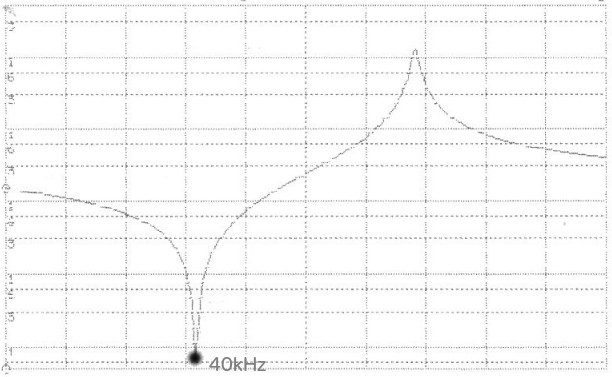
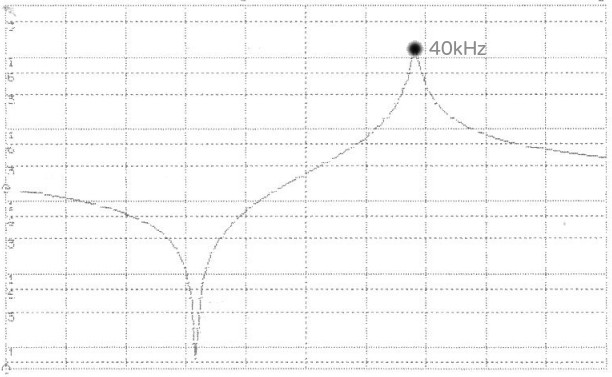
When transmitting, it is most common to operate the air transducer at its frequency of minimum impedance, or resonant frequency (Fr). See Figure 2. Transmitting at this frequency generates the highest output signal for the input power applied and is therefore the most efficient driving condition. When using an air transducer in a receiving application, it is more efficient to receive signals at the frequency of maximum impedance, or anti-resonant frequency (Fa). See Figure 3. This condition maximizes the signal generated by the transducer as the result of a mechanical stimulus, or incoming acoustic signal. The result? 40kHz air transducer transmitters operate at Fr=40kHz, while 40 kHz air transducer receivers operate at Fa=40kHz.
Figure 2: Typical impedance plot showing resonant
frequency (Fr) at 40kHz for a 40kHz air transducer
transmitter
Figure 3: Typical impedance plot showing
anti-resonant
frequency (Fr) at 40kHz
for a
40kHz air transducer
receiver
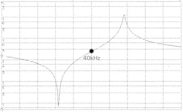
These optimized conditions are great, if there is enough space for dedicated transmitting and receiving transducers, but this is often not the case. Therefore, air transducer "transceivers" are also fairly common. In a "transceiver" application the air transducers Fa and Fr frequencies are centered around the 40kHz operating frequency, and drive circuits and signal post processing techniques can fill in the gaps resulting in perfectly useful signals for many applications. See Figure 4.
Figure 4: Typical impedance plot showing resonant
frequency (Fr) and anti-resonant frequency
centered around
40kHz for a 40kHz air
transducer
transceiver
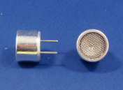
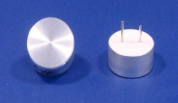
Physically, air transducers are generally available in "open face" or "environmental" enclosures. Open face transducers generally are open to the atmosphere, are more efficient (not having to transmit through a housing), and often contain a focusing cone to assist in beam development and accuracy. See Figure 5. Environmentally packaged air transducers are sealed to the atmosphere, ideal for damp or harsh environments, but operate at reduced efficiencies as a result of the housing material. See Figure 6. Common housing materials are various types of metal including aluminum and stainless steel, or plastics, depending on the environmental requirements.
Figure 5: Air transducer in aluminum
open housing. Also available in
plastic housing.
Notice the
f
ocusing
cone inside?
Figure 6: Air transducer in environmental
aluminum housing. Also available in
plastic housing. Transducer face is
completely sealed from the elements
APC offers
standard piezoelectric air transducers
that contain a piezoelectric ceramic element that is mounted in an aluminum, plastic, or environmental housing and are available for quick delivery! Our air transducers are available in 25, 40 and 300 kHz signal frequency.
- High sensitivity
- Excellent sound pressure level
- Stable electrical and mechanical characteristics
- Available in 10mm to 25mm diameter
- Available in matched pairs
- Competitively priced
- Available for fast delivery
- Short distance measurement (~1.5" - 10")
- Object detection
- Level sensing
- High frequency transmitter/receiver
- See Spec Sheet 10-3300 (air transducer and module combination)
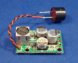
Figure 7: APC 300kHz open plastic housing
air transducer and driver board combo
Don't see a standard air transducer that will work for your piezo system? APC also offers custom designed air transducers!