| AFM Success Requires Optical Microscopy |
An integrated, high-quality optical microscope is essential for the efficient use of an Atomic Force Microscope (AFM). An optical microscope on an AFM enables users to:
- Align the laser onto the cantilever
- Locate specific surface features on a sample for AFM scanning
- Conduct successful probe approach
To facilitate optimal results with an AFM, the optical microscope needs to have high resolution, a mechanical focus, a large zoom range, and high magnification.
|
Aligning the AFM Laser onto the Cantilever
Most commercial AFMs utilize a light-lever force sensor which reflects a focused laser from the back side of a cantilever. The cantilevers can be 20-30 microns wide by 50-300 microns long. The cantilever, cantilever chip, and the probe work together as a coordinated unit, and are micro-machined.
Some AFMs offer 'pre-aligned' cantilever/cantilever chip/probe units, theoretically eliminating the task of properly landing and reflecting the laser on the back side of the cantilever. The pre-aligned concept ends up being a challenge to achieve due to the impacts of contamination, the subtle variations in cantilever dimensions, and human error. Thus, even with a 'pre-aligned' design, it becomes necessary to include a mechanical adjustment mechanism on the AFM so that the user can physically move the focused laser beam onto the cantilever. An optical microscope makes a big difference when the AFM user, whether working with a pre-aligned cantilever or a user-aligned cantilever, manually positions the focused laser properly onto the cantilever's back side.
|
|
|
|
In the image on the left, the optical microscope view shows how a focused laser beam is incorrectly placed on the AFM's cantilever chip. The cantilever chip supports the cantilever. In the image on the right, the optical microscope reveals that laser and cantilever are now properly aligned: the beam is at the end of the cantilever. (Both images are focused on the cantilever, not on the sample.)
|
|
Locating Sample Surface Features for AFM Scanning
AFMs typically have scan ranges that are less than 100 microns. This means it's not possible to view large surface areas - or to "get the big picture". That makes sense when you consider you're trying to visualize very small objects, but the problem becomes trying to 'find' the important areas of the sample. For example, the area of interest may be on isolated areas of the sample. A high-quality optical microscope enables the user to rapidly make determinations about the areas of a sample to scan with the AFM. Having a large optical zoom ratio is really helpful: at low magnification the user can find the general area for scanning, and at high magnification the user can find specific areas for AFM scanning.
|
|
|
|
Left: A Low magnification view from the optical microscope of a test structure, with AFM probe/cantilever on the right of the view. This large view facilitates finding a particular feature for AFM scanning.
Right: A higher magnification optical microscope view of the same test structure shows how, once the user has found a particular feature for scanning, the user can then move the AFM probe to a position just above the region to be scanned. The optical microscope is focused on the sample surface; as the probe is above the surface, it is not in focus.
|
|
Conducting Successful Probe Approach
In an
Atomic Force Microscope (AFM) the probe tip must be moved to a point where it interacts with the various forces associated with a sample's surface. To make the tip's approach to the sample faster, it is helpful to get the probe as close to the surface as possible before utilizing an automated tip approach algorithm. This probe approach is facilitated with an optical microscope in two ways:
|
|
|
|
The left view from an optical microscope shows that when the probe is away from the sample surface, the laser's spot is a distance from the cantilever. Additionally, when the probe is not on the surface, only the sample or the cantilever will be in focus. The right view shows that when the probe reaches the sample surface, both the cantilever and the sample are in focus, and the two laser spots overlap.
|
|
Three Viewing Orientations for Optical and Atomic Force Microscope Combinations
The viewing orientations of the optical microscope in relation to the AFM probe, cantilever, and sample are:
- top view
- bottom view
- 45 degree angle view
The
top view is the most popular optical microscope orientation with the AFM. The optical microscope is placed directly above the AFM cantilever, yielding an optical view of the top of the AFM cantilever and the top of the surface of the sample to be imaged. Typically, a uniaxial light source is required for a top view microscope.
|
|
|
Left, the TT-AFM stage with top view optical microscope with zoom tube, xy translator, focus control, and CMOS camera.
Right, a top-view image of a probe in close proximity to a feature
of interest.
|
|
The
bottom view
is possible with an inverted light microscope (ILM). In this configuration, the user can view the sample cantilever from the bottom. This type of view is very helpful for life sciences applications,and is popular for other types of microscopy such as flourescence microscopy.
|
|
|
|
Left, an inverted light microscope's view of the AFM probe. Right, an inverted light microscope's image of a cell and an AFM cantilever, with an area of interest highlighted for AFM scanning.
|
|
The 45 degree angle view can be helpful for probe approach, but it is not necessary if the optical microscope's top-view optic has a decent focus control.
|
|
|
| Three views of the same e. coli sample, from AFMWorkshop's LS-AFM: L to R: video optical microscope, inverted optical microscope, and atomic force microscope. The area in red indicates sample area selected for AFM scanning. |
|
|
|
- January 11-15, 2016
- March 14-18, 2016
Learn to Build, Operate and Repair your Own TT-AFM
Signal Hill, California
|
 |
|
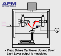
A still shot from animated series #2 on Vibrating Mode for AFMs
|
|
A very popular step-by-step animation series, currently includes :
|
from Oxford University Press, by Peter Eaton and Paul West. Order yours today from Amazon.com.
"...a great introduction to AFMs for beginners and also serves as a good starting point for more serious users."
Udo D. Schwarz,
Yale University
|
|
|


